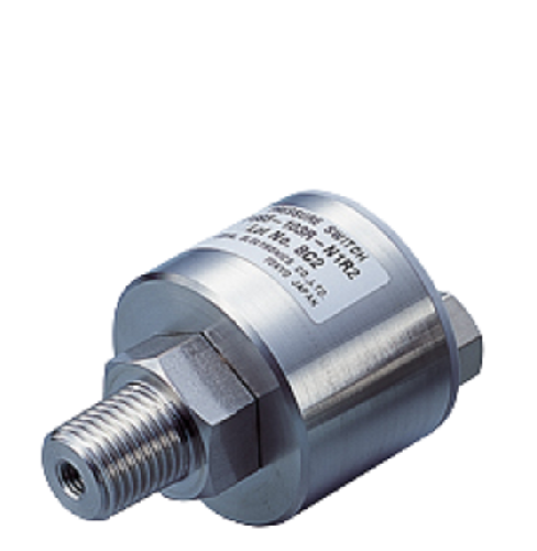
| Product: | Pressure switch |
| Manufacturer: | Nidec Copal |
| Features: | 1. High corrosion resistance and drip-proof construction. Pressure port attachment made of SUS 316L. Proven IP-65 grade gauge body (IP-65 in accordance with IEC). |
| 2. Standard product provides two switch outputs. | |
| 3. Absolute pressure type and compound pressure type which can control negative to positive pressure with only a single pressure gauge are all in line | |
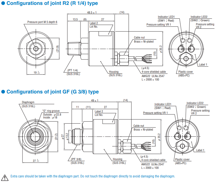
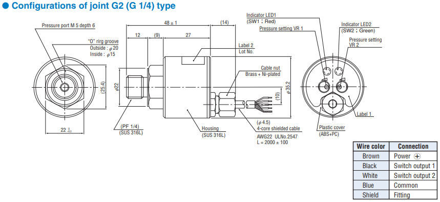
| 4. 3 standard types of joint are provided R2: R 1/4 with M 5 female screw GF: G 3/8 with flash diaphragm G2: G 1/4 with M 5 female screw |
Contact
| Specifications | |
| Packaging method: | Bag |
| Installation type: | Please refer to the product spec |
| Operating temp: | Please refer to the table below |
| Ampacity: | Please refer to the table below |
| Rated voltage: | -20°C ~ 80°C |
| Size (mm) (L*W*H): |
27X21.5 27X31.2 |
| note | For further information, please contact:+886-3-4266335 |
General specifications |
|
| Pressure medium: | Corrosive gases/liquids compatible with SUS 316L |
| Pressure reference: | Gauge |
| Output: | NPN/PNP Open collector |
| Ports: | R 1/4, G 3/8,G1/4 |
General specifications
- Unless otherwise specified, the specs are defined at an ambient temperature of 25±5 °C and excitation voltage of 12 V DC.
| Item | 102R | 352R | 103R | 102A |
|---|---|---|---|---|
| Pressure reference: | Gauge | Absolute | ||
| Rated pressure range: | −100 ~ 100kPa | − 100 ~ 350kPa | −100 ~ 1000kPa | 100 (abs) |
| Maximum pressure: | 200kPa | 700kPa | 2000kPa | 200 (abs) |
| Break-down pressure: | 300kPa | 1050kPa | 3000kPa | 300 (abs) |
| Operating temp. range: | − 20 ~ 80°C | |||
| Compensated temp. range: | 0 ~ 50°C | |||
| Operating humidity: | 35 ~ 85%RH(No condensation) | |||
| Storage temp.: | −20 ~ 80°C(Atmospheric pressure, humidity 65 %RH maximum) | |||
| Pressure medium: | Corrosive gases/liquids compatible with SUS 316L | |||
| Insulation resistance: | 100 MΩ min.(500 V DC) | |||
| Dielectric strength: | 800 V AC, 60 s(Leakage current 1 mA maximum) | |||
| Sealed liquid: | Silicone oil | |||
| Pressure port: | R 1/4、G 3/8(Flash diaphragm)、G 1/4 ※ 1 | |||
| Net weight: | R2 : Approx. 165g, GF : Approx. 180g, G2 : Approx. 170g | |||
| Drip-proof structure: | IP65 | |||
| Supply voltage: | 10.8 ~ 30VDC(Including ripple percentage) | |||
| Consumption current: | 20 mA max. | |||
※ 1 An “O” ring is provided as accessory. (G 3/8 : P18, G 1/4 : P15)
Switch output
| No. of outputs: | 2 |
|---|---|
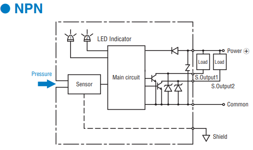
| Output interface: | Open collector output (NPN or PNP) |
| Setting method: | Adjustable by VR |
| Adjustable range: | 0 ~ 100 %/102A:0 ~ 108 % |
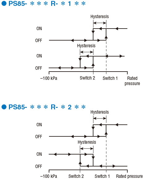
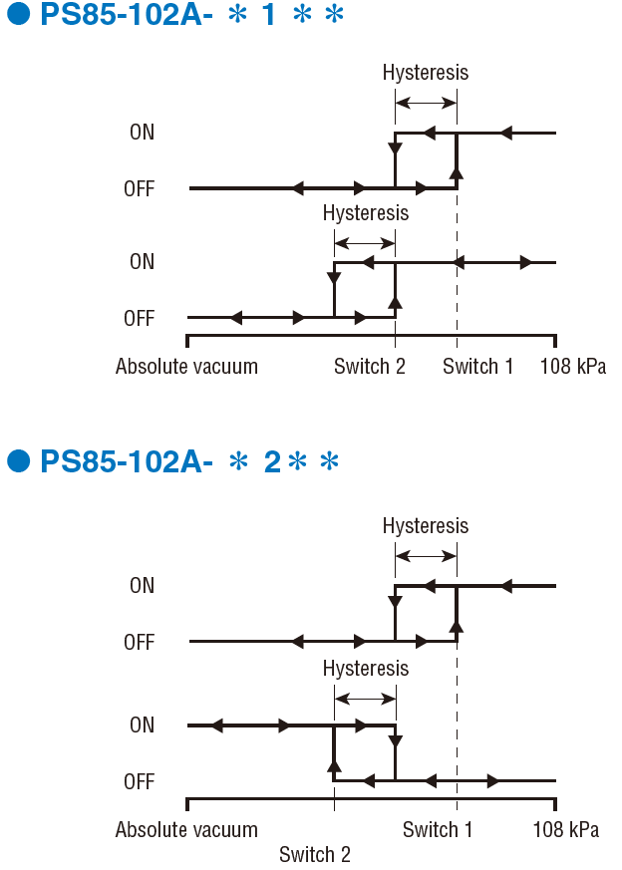
| Output mode: | Upper and upper limite mode/Upper and lower limite mode |
| Display: | SW1 : Red LED ON, SW2 : Green LED ON |
| Accuracy 0 ~ 50 °C (Reference temp.: 25 °C): |
± 0.3 %F.S. |
| Hysteresis: | 2%F.S. maximum |
| Switching capacity: | 30 V 100 mA maximum |
| Residual voltage: | 0.8 V maximum(NPN), 1.2V maximum (PNP) |
| Response: | Approx. 2ms |
An “O” ring is provided as accessory. (G 3/8 : P18, G 1/4 : P15)
ENVIRONMENTAL CHARACTERISTICS
| Test item | Test conditions (At 25 ± 5 °C) | Permissible change |
|---|---|---|
| Vibration: | 10 ~ 500 Hz, 1.5 mm maximum/98.1 m/s2 , 3 directions for 2 hours each | Switch output setting: ± 1 %F.S. maximum |
| Shock: | 490 m/s2 , 3 directions for 3 times each | |
| Moisture resistance: | 40 °C, 90 ~ 95 %RH, 240 hrs | |
| Pressure cycling: | 0 ~ Rated pressure, 106 cycles |
MODEL NUMBER DESIGNATION |
|||
| PS85- | 102 R | N1 | R2 |
| Series name | Pressure reference /Rated pressure range | Switch output interface | Fitting |
|
R:Compound |
N1:NPN open collector(Upper and upper limit mode) N2:NPN open collector(Upper and lower limit mode) P1:PNP open collector(Upper and upper limit mode) P2:PNP open collector(Upper and lower limit mode) |
R2:R 1/4(M 5 female screw) |
|
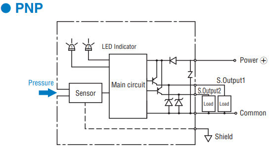
SWITCH OUTPUT SCHEMATICS
INTERNAL ELECTRICAL SCHEMATICS
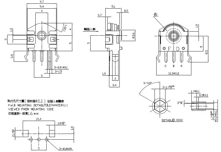
| 外型尺寸 |
Back